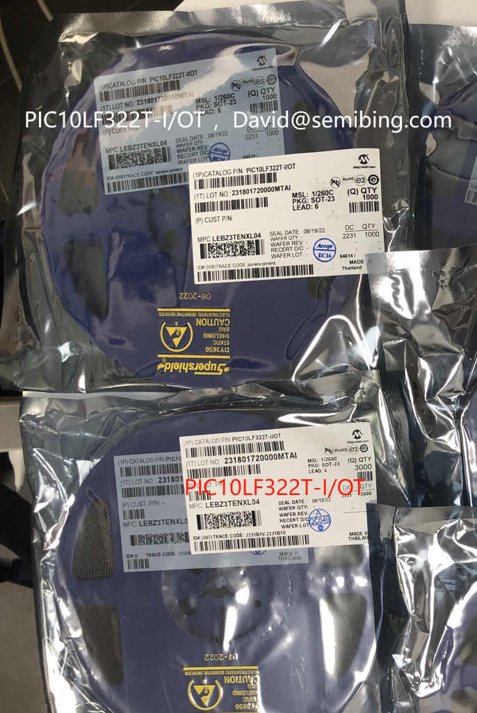
The PIC10LF322T-I/OT is a microcontroller from Microchip Technology with the following features and specifications:


PIC10LF322T-I/OT Key Features:
- Core: 8-bit PIC® MCU
- Operating Voltage: 1.8V to 3.6V
- Flash Program Memory: 896 Bytes
- RAM: 64 Bytes
- EEPROM: 128 Bytes
- I/O Pins: 4
- Package: SOT-23-6
- Peripherals:
- Enhanced Timer (TMR2)
- 8-bit Analog-to-Digital Converter (ADC)
- Configurable Logic Cell (CLC)
- Numerically Controlled Oscillator (NCO)
- Complementary Waveform Generator
PIC10LF322T-I/OT Additional Details:
- Low Power Consumption: Ideal for battery-powered applications.
- Wide Operating Voltage Range: Suitable for a variety of power supplies.
- Integrated Peripherals: Useful for signal measurement, control, and generation tasks.
PIC10LF322T-I/OT Applications:
- Portable devices
- Sensor interface
- Small form factor applications
- Consumer electronics
For more detailed information, you can refer to the official datasheet from Microchip Technology:
https://ww1.microchip.com/downloads/en/DeviceDoc/40001585D.pdf
Using the PIC10LF322T-I/OT microcontroller involves several steps, from setting up the hardware to writing and uploading code to the microcontroller. Here’s a basic guide to get you started:
PIC10LF322T-I/OT 1. Set Up the Hardware:
PIC10LF322T-I/OT Tools and Materials Needed:
- PIC10LF322T-I/OT microcontroller
- Breadboard and jumper wires (if prototyping)
- Power supply (1.8V to 3.6V)
- Capacitors (for power stabilization)
- Programming tool (e.g., PICkit 3 or PICkit 4)
- PC with MPLAB X IDE installed
PIC10LF322T-I/OT Connections:
- Power: Connect VDD to the positive supply voltage and VSS to the ground.
- Programming Pins: Connect the ICSP (In-Circuit Serial Programming) pins (VPP/MCLR, ICSPDAT, and ICSPCLK) to the corresponding pins on the programmer.
- I/O Pins: Connect any additional components (sensors, LEDs, etc.) to the appropriate I/O pins.
PIC10LF322T-I/OT 2. Install Software:
PIC10LF322T-I/OT MPLAB X IDE:
- Download and install MPLAB X IDE from Microchip’s official website.
- Optionally, install MPLAB Code Configurator (MCC) to help with code generation.
PIC10LF322T-I/OT XC8 Compiler:
- Download and install the XC8 compiler, which is necessary for compiling code for PIC microcontrollers.
PIC10LF322T-I/OT 3. Create a New Project:
- Open MPLAB X IDE:
- Go to
File->New Project. - Select
Microchip Embedded->Standalone Project. - Choose your device (PIC10LF322T).
- Select the programmer (e.g., PICkit 3).
- Name your project and select a location to save it.
- Configure the Project:
- If using MCC, open it via
Tools->Embedded->MPLAB Code Configurator. - Use MCC to configure device settings, peripherals, and generate initialization code.
PIC10LF322T-I/OT 4. Write Your Code:
- Initialize Peripherals:
- Set up configuration bits (oscillator settings, watchdog timer, etc.).
- Initialize any peripherals you plan to use (ADC, timers, etc.).
- Main Code:
- Write your main application code in the
main.cfile. Here’s a simple example that blinks an LED:
   // Include necessary header files
   #include <xc.h>

   // Configuration bits
   #pragma config FOSC = INTRCIO  // Internal oscillator
   #pragma config WDTE = OFF      // Watchdog Timer disabled
   #pragma config PWRTE = ON      // Power-up Timer enabled
   #pragma config MCLRE = OFF     // MCLR pin function is digital input
   #pragma config CP = OFF        // Code protection is disabled
   #pragma config BOREN = ON      // Brown-out Reset enabled
   #pragma config CLKOUTEN = OFF  // CLKOUT function is disabled

   void main(void) {
       TRISAbits.TRISA0 = 0; // Set RA0 as output (LED)
       while (1) {
           LATAbits.LATA0 = 1; // Turn on LED
           __delay_ms(500);    // Delay 500 ms
           LATAbits.LATA0 = 0; // Turn off LED
           __delay_ms(500);    // Delay 500 ms
       }
   }
PIC10LF322T-I/OT 5. Compile and Program:
- Build the Project:
- Click on the
Buildbutton (hammer icon) to compile your code.
- Program the Microcontroller:
- Connect the programmer to your PC and the microcontroller.
- Click on the
Make and Program Devicebutton (downward arrow icon) to upload the code to the microcontroller.
PIC10LF322T-I/OT 6. Test Your Setup:
- Power the microcontroller and observe the behavior of your application (e.g., the LED should blink).
PIC10LF322T-I/OT 7. Debugging:
- Use MPLAB X IDE’s debugging tools to troubleshoot and refine your code.
This is a basic guide to get you started with the PIC10LF322T-I/OT microcontroller. For more detailed information, refer to the PIC10LF322T datasheet and Microchip’s documentation and application notes.
Other Hot parts from semibing with real stock with Discount :

3, MCP2003A-E/MD ,MICROCHIP,
![]()
5,PIC16F15356T-I/SS ,MICROCHIP,![]()
6,PIC18LF4321-I/PT ,MICROCHIP,![]()
7, DMP2100U-7, DIODES ,SOT-23,![]()
8, NSR0530HT1G ,onsemi ,Diode Schottky, SOD323![]()
9, PAM2421AECADJR ,DIODES, SOP-8/SOIC-8-EP ,![]()
10, CESDLC5V0K5, CJ,,SOT-363,![]()
11, GP3420,Green Power , SOT-23/MOS,![]()
12, BSS84,,Green Power,MOSFET, P-Ch, SOT-23 ,![]()
13,JR8214 单键触摸PWM无极调光台灯芯片 ,劲锐佳JINRUIJIA,深圳劲锐佳科技有限公司![]()
15,JR8214 单键触摸PWM无极调光台灯芯片 ,劲锐佳JINRUIJIA,深圳劲锐佳科技有限公司