2000pcs of FAN7621BSJX or FAN7621SJX in stock for sale ,ON fairchild, new and original

Brief Introduction of FAN7621BSJX or FAN7621
The FAN7621BSJX or FAN7621SJX is a pulse frequency modulation controller for high-efficiency half-bridge resonant converters.Offering everything necessary to build a reliable and robust resonant converter, the FAN7621B simplifies designs and improves productivity, while improving performance. The FAN7621B includes a highside gate-drive circuit, an accurate current controlled oscillator, frequency limit circuit, soft-start, and built-in protection functions. The high-side gate-drive circuit has a common-mode noise cancellation capability, which guarantees stable operation with excellent noise immunity. Using the zero-voltage-switching (ZVS) technique dramatically reduces the switching losses and efficiency is significantly improved. The ZVS also reduces the switching noise noticeably, which allows a small-sized Electromagnetic Interference (EMI) filter. The FAN7621B can be applied to various resonant converter topologies; such as series resonant, parallel resonant, and LLC resonant converters.
Features of FAN7621BSJX or FAN7621
| Features | |
| Variable Frequency Control with 50% Duty Cycle for Half-bridge Resonant Converter Topology | |
| High Efficiency through Zero Voltage Switching (ZVS) | |
| Fixed Dead Time (350ns) | |
| Up to 300kHz Operating Frequency | |
| Pulse Skipping for Frequency Limit (Programmable) at Light-Load Condition | |
| Remote On/Off Control using CON Pin | |
| Protection Functions: Over-Voltage Protection (OVP), Overload Protection (OLP), Over-Current Protection (OCP), Abnormal Over-Current Protection (AOCP), Internal Thermal Shutdown (TSD) |
| Applications |
| PDP TV LCD TV Desktop PC Server Video Game Console |
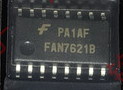
FAN7621BSJX FAN7621SJX, PFM CONTROLLER FOR HALF-BRIDGE
Converter Offline Half-Bridge Topology Up to 300kHz 16-SOP
Product Attributes
Categories: Integrated Circuits (ICs)
PMIC – AC DC Converters, Offline Switchers
Manufacturer: ON Semiconductor
Packaging: Tape & Reel (TR)
Part Status: Active
Output Isolation: Isolated
Internal Switch(s): No
Voltage – Breakdown
Topology Half-Bridge
Voltage – Start Up 12.5V
Voltage – Supply (Vcc/Vdd) 10V ~ 25V
Duty Cycle 50%
Frequency – Switching Up to 300kHz
Power (Watts) 192W
Fault Protection Current Limiting, Over Load, Over Temperature, Over Voltage
Control Features Frequency Control
Operating Temperature -40°C ~ 130°C (TJ)
Package / Case 16-SOIC (0.209″, 5.30mm Width)
Supplier Device Package 16-SOP
Mounting Type:Surface MountFAN7621B — PFM Controller for Half-Bridge Resonant Converters
FAN7621B
PFM Controller for Half-Bridge Resonant Converters
FAN7621BSJX or FAN7621SJX Features:
1,Variable Frequency Control with 50% Duty Cycle
for Half-bridge Resonant Converter Topology
2, High Efficiency through Zero Voltage Switching (ZVS)
3, Fixed Dead Time (350ns)
4, Up to 300kHz Operating Frequency
5, Pulse Skipping for Frequency Limit (Programmable)
at Light-Load Condition
6, Remote On/Off Control using CON Pin
7, Protection Functions: Over-Voltage Protection
(OVP), Overload Protection (OLP), Over-Current
Protection (OCP), Abnormal Over-Current Protection
(AOCP), Internal Thermal Shutdown (TSD)
Applications
8, PDP and LCD TVs
9, Desktop PCs and Servers
10, Adapters
11, Telecom Power Supplies
12, Video Game Consoles
The FAN7621BSJX FAN7621SJX is a pulse frequency modulation,
controller for high-efficiency half-bridge resonant
converters. Offering everything necessary to build a
reliable and robust resonant converter, the FAN7621B
simplifies designs and improves productivity, while
improving performance. The FAN7621B includes a high-
side gate-drive circuit, an accurate current controlled
oscillator, frequency limit circuit, soft-start, and built-in
protection functions. The high-side gate-drive circuit has
a common-mode noise cancellation capability, which
guarantees stable operation with excellent noise
immunity. Using the zero-voltage-switching (ZVS)
technique dramatically reduces the switching losses and
efficiency is significantly improved. The ZVS also
reduces the switching noise noticeably, which allows a
small-sized Electromagnetic Interference (EMI) filter.
The FAN7621B can be applied to various resonant
converter topologies; such as series resonant, parallel
resonant, and LLC resonant converters.
Related Resources
AN4151 — Half-bridge LLC Resonant Converter Design
using FSFR-series Fairchild Power Switch (FPS TM )
FAN7621BSJ
-40°C ~ 130°C 16-Lead Small Outline Package (SOP)
-50 -25 0 25 50 75 100
Temp ( O C)
Normalized at 25 O C
Figure 14. CON Pin Enable Voltage vs. Temperature Figure 15. OCP Voltage vs. Temperature
© 2009 Fairchild Semiconductor Corporation www.fairchildsemi.com
FAN7621B • Rev. 1.0.1 9
FAN7621B — PFM Controller for Half-Bridge Resonant Converters
Functional Description
1. Basic Operation: FAN7621B is designed to drive
high-side and low-side MOSFETs complementarily with
50% duty cycle. A fixed dead time of 350ns is introduced
between consecutive transitions, as shown in Figure 16.
High-side
MOSFET
gate drive
Low-side
MOSFET
gate drve
Dead time
time
Figure 16. MOSFETs Gate Drive Signal
2. Internal Oscillator: FAN7621B employs a current-
controlled oscillator, as shown in Figure 17. Internally,
the voltage of R T pin is regulated at 2V and the charging
/ discharging current for the oscillator capacitor, C T , is
obtained by copying the current flowing out of R T pin
(I CTC ) using a current mirror. Therefore, the switching
frequency increases as I CTC increases.
Figure 17. Current Controlled Oscillator
3. Frequency Setting: Figure 18 shows the typical
voltage gain curve of a resonant converter, where the
gain is inversely proportional to the switching frequency
in the ZVS region. The output voltage can be regulated
by modulating the switching frequency. Figure 19 shows
the typical circuit configuration for R T pin, where the
opto-coupler transistor is connected to the R T pin to
modulate the switching frequency.
Figure 21. Internal Block of Control Pin
Protection: When the control pin voltage exceeds 5V,
protection is triggered. Detailed applications are
described in the protection section.
Pulse Skipping: FAN7621B stops switching when the
control pin voltage drops below 0.4V and resumes
switching when the control pin voltage rises above 0.6V.
To use pulse-skipping, the control pin should be
connected to the opto-coupler collector pin.
© 2009 Fairchild Semiconductor Corporation www.fairchildsemi.com
FAN7621B • Rev. 1.0.1 13
FAN7621B — PFM Controller for Half-Bridge Resonant Converters
6. PCB Layout Guideline: Duty imbalance problems
may occur due to the radiated noise from main
transformer, the inequality of the secondary-side leakage
inductances of main transformer, and so on. Among
them, it is one of the dominant reasons that the control
components in the vicinity of R T pin are enclosed by the
primary current flow pattern on PCB layout. The direction
of the magnetic field on the components caused by the
primary current flow is changed when the high-and-low
side MOSFET turns on by turns. The magnetic fields with
opposite direction from each other induce a current
through, into, or out of the R T pin, which makes the turn-
on duration of each MOSFET different. It is strongly
recommended to separate the control components in the
vicinity of R T pin from the primary current flow pattern on
PCB layout. Figure 28 shows an example for the duty-
balanced case. The yellow and blue lines show the
primary current flows when the lower-side and higher-
side MOSFETs turns on, respectively. The primary
current does not enclose any component of controller.
In addition, it is helpful to reduce the duty imbalance to
make the loop configured between CON pin and opto-
coupler as small as possible, as shown in the red line in
Figure 28.
Figure 28. Example for Duty Balancing
© 2009 Fairchild Semiconductor Corporation www.fairchildsemi.com
FAN7621B • Rev. 1.0.1 14
FAN7621B — PFM Controller for Half-Bridge Resonant Converters
Typical Application Circuit (Half-Bridge LLC Resonant Converter)
Application Device Input Voltage Range Rated Output Power
Output Voltage
(Rated Current)
LCD TV FAN7621B
390V DC
(340~400V DC )
192W 24V-8A
Features
High efficiency ( >94% at 400V DC input)
Reduced EMI noise through zero-voltage-switching (ZVS)
Enhanced system reliability with various protection functions
FAN7621
FAN7621B — PFM Controller for Half-Bridge Resonant Converters
Typical Application Circuit (Continued)
Usually, LLC resonant converters require large leakage inductance value. To obtain a large leakage inductance,